")
")
The Wick
What would even the best kerosene/paraffin burner in the world be without its wick? The wick is an essential component of every kerosene/paraffin lamp, because it transports the kerosene/paraffin from below, from the font, up to the top of the wick tube so that it can be burnt there. No kerosene/paraffin burner can function without a wick. Of course, this statement does not apply to gas lamps that burn a gas, nor to high-pressure incandescent lamps that burn kerosene/paraffin or spirit but do not need a wick, because these liquids are gasified under pressure before they are burnt.
So far, there has always been talk of flat wicks, tubular wicks, etc. Now it is time to take a closer look at the wick. The wick is a textile fabric made of cotton threads woven together in a specific pattern. Cotton has proven to be the ideal natural material for wicks. Of course, wicks have also been woven and tested with other materials. Wick producers even thought of making wicks from super-thin glass fibres, because such wicks would never wear out. But in the end, no material was as good and as economical as cotton.
The Capillary Pressure
How does a fuel liquid, be it vegetable oil or mineral oil, creep upwards from below, exactly opposite to the earth's gravitational force? One normally thinks that nothing will move upwards unless it is forced to do so by an external force (e.g. by means of a pump). The upward creep of a liquid through a textile fabric is no exception. An external force also acts here, which in physics is called "capillary pressure". I will try to explain it here in a relatively simple and hopefully understandable way.
All textile fabrics that are woven together from any thin threads contain lots of tiny, empty spaces between these threads. These empty spaces between the threads are called capillaries. The capillaries can be completely disparate, of quite different sizes, and distributed quite chaotically (e.g. in handmade papers), or they can be quite orderly, elongated and of comparable dimensions (e.g. in cords made of several threads twisted together lengthwise). As soon as the capillaries are ordered and oriented in the longitudinal direction, and as soon as they have fallen below a certain diameter, they exert the so-called capillary pressure on the liquid with which they are wetted.
Capillary pressure occurs because the molecules of the liquid and the molecules on the surfaces of the textile fabric attract each other. This mutual attraction is caused by the chemical-physical properties of these molecules. The greater this attraction, the more the liquid molecules wet the surface of the threads and are held there. Due to the strength of this attraction, more and more molecules of the liquid try to wet the still free, not yet wetted surfaces of the threads and are in turn held there. Other molecules follow in order to reach free areas further up. The liquid thus begins to slowly but noticeably "creep" upwards. This physical force of attraction is the external force mentioned above. This force is called "capillary pressure", a pressure that makes the liquid move upwards, even against the force of gravity!
Well, there are some factors that significantly influence this force. The chemical compositions of the liquid and the solid walls of the capillaries create the necessary physical attraction of these two substances. Without this attraction, no wetting of the surfaces with a liquid would occur anyway. In addition, the narrowness of the capillary channels, i.e. their diameter, plays a major role. The narrower, smaller the capillaries, the stronger the resulting capillary pressure. Other important factors are the weight and viscosity of the liquid. After all, the weight causes an increase in the earth's gravitational pull downwards. A heavy liquid, e.g. mercury, can hardly rise upwards. Viscosity is a measure of the free mobility of the liquid molecules. A liquid is always less viscous, i.e. thin, when its molecules are small, short and unbound to each other. This makes these molecules very easy to move; they can quickly wet the capillary walls and rise up again and again. Just imagine what happens when you dip the end of a wick into honey. Almost nothing; because honey is firstly heavy, and secondly very viscous, so not very flow-friendly.
After this long excursion into the world of physics, we now come back to our wick. The wick is spun from cotton threads, relatively densely and in a longitudinal direction. This is exactly the prerequisite for narrow, elongated capillaries. If you compare kerosene/paraffin with a vegetable oil (e.g. olive oil), you will find that kerosene/paraffin is lighter and more mobile (less viscous) than oil. Despite relatively similar chemical composition, kerosene/paraffin therefore creeps up the wick much better than oil. Especially when the kerosene/paraffin in the font has become warmer over time, its viscosity decreases further; it becomes even thinner. This was one of the reasons why kerosene/paraffin could easily outrun vegetable oil.
Differently Woven Wicks
Well, every collector will have noticed at some point that different wicks burn differently well, even if they are operated with the same burner and with the same kerosene/paraffin. Although the wicks are all spun from cotton threads, they are made from differently pre-treated threads and are also woven differently densely. The capillary pressure is strongly dependent on how large the capillaries are. The weave density influences the capillary sizes and thus also the capillary pressure considerably. I have the impression that newly made wicks no longer have the quality of the old wicks, presumably because the wick manufacturers now no longer have the know-how to do this very well. For this reason, I am anxious to leave the old wick of a burner still on it at all costs, however shabby it may look. If you are forced to use a new wick because the original wick has been lost, then you should at least wash the new wick first (30°-40°C hand wash) to remove the finish that is applied in the weaving process to make the threads more slippery, because this also reduces the capillary pressure.
In the past, in the times of the stormy development of ever better kerosene/paraffin burners in the last third of the 19th century, every development step was consistently used to achieve a higher brightness. One even strove to develop the optimally adapted wick for each burner. There were wicks of different densities and thicknesses, depending on which burner they were to be used in. The quality of the cotton threads was also adapted accordingly. I am not an expert, but I can well imagine that the wick manufacturers of the time experimented with different thread qualities (such as double or triple twisted, long fibrillated or combed threads).
Comment of Jac van de Walle from Sulz am Neckar (Germany): He has noticed that the Kosmos burners smell slightly of "oil heating" when they are fitted with a wick of poor quality. The wick then transports less fuel, and you have to raise it higher to get a good flame. Then the lamp burns with a good, high flame. But the burner actually burns more kerosene/paraffin directly from the wick without completely gasifying it beforehand. Result: The lamp smells, although the flame looks good. A new quality wick provides a remedy. The flame is equally high, but the wick then sits deeper in the wick tube, and the smell is then almost gone, but not completely. The Matador burners don't smell at all. These are actually almost like carburettor burners because the flame disc on top gets very hot and dissipates the heat to the wick tube, which promotes the necessary gasification of the fuel before combustion. But the consumption is more than twice as high.
Burners with Unusual Wick Concepts
So it is no wonder that even complicated burners were developed whose kerosene/paraffin supply ran via two separate types of wick. These burners (e.g. the Sonnenbrenner by R. Ditmar or the Brillant burner by Gebr. Brünner, both in Vienna) had a special, coarse-meshed, soft suction wick or transport wick that transported as much kerosene/paraffin as possible upwards and delivered the fuel to the actual burning wick via a relatively large contact surface. High quality British duplex burners also had a transport wick placed in the middle of the two flat wicks. However, this wick only served to support the actual flat wicks of the burner during fuel transport. Wild & Wessel had developed very special wicks with suction strands for their Vulkan and Central Vulkan burners. With their special flame discs and suitably constructed glass chimneys, such burners produced a very calm, brightly burning flame. They were developed for the highest demands and were therefore correspondingly expensive.

Different types of wick
From left: Full wick (a narrow and a wide one)
Flat wick (here with fringes)
Tubular wick
Wick of Central Vulkan burner with suction strands
Sonnenbrenner (= Sun burner), at the bottom the transport wick, at the top the burning wick (here the outer wick tube is removed).
Transport wick at duplex burners (wick with the darker colour in the middle)
The Wick Drive with Gears
Every kerosene/paraffin burner has a wick through whose capillaries the kerosene/paraffin can raise and burn at the end of the wick tube. Some burners have two wicks (duplex burners, Martin burners) and even three wicks (triplex burners). Mitrailleuse burners can even have up to 20 wicks. The wicks are adjusted in height with the wick knobs to change the flame height and thus the light intensity. The actual wick drive system of the burner is connected to the wick knob.
Shortly after Argand's oil burner was invented, the tubular wick, which was movably mounted between two concentric pipes, was connected to a metal rod that protruded from the side of the two pipes. With this rod, one could regulate the height of the wick and thus also the height of the flame as desired. A few years later, this rod, which had to be adjusted by hand, had been replaced with a vertically movable rack, the height of which could now be adjusted more easily and precisely with a permanently attached gear wheel. To facilitate manual operation, this gear wheel was connected to a round, flat disc. This practically invented the wick knob, which was later used in almost all kerosene/paraffin burners.
This complicated-looking mechanism consisting of a rack connected to the tubular wick and a gear wheel to move the rack was later, when flat burners dominated the newly heralded kerosene/paraffin lamp era, greatly simplified by eliminating the rack and letting the gear wheel act directly on the wick. To do this, the axle of the wick knob was extended into the burner and, depending on the size of the burner, 2-3 smaller gearwheels were attached to this shaft, which engaged laterally with the wick. The wick was now moved directly with the gear wheels instead of the rack. This type of wick movement is called wick drive with gear wheels.
This simplified wick drive with the gears was also retained in the round burners invented a short time later, but now with the difference that instead of 2-3 gears on one axis, four gears were operated on two parallel axes, since the wick used was much wider and consequently gears were needed at four different points to move the wick uniformly up or down (see the evolution of the wick drive with gears in the Kosmos burners by Wild & Wessel in the subchapter The Kosmos Burner). The second parallel axle did not need its own wick knob, as the two gears on this axle were turned by the other two gears. In a Belgian centrer-draft burner by Moreau Frères, there are even three axles arranged like the sides of a triangle. On this burner, 3 wider gears engage with the tubular wick.

Wick drive with gear wheels
From left: Flat burner (1 axle, 3 gears)
Duplex burner, sawed off at the bottom (2 axles with 2 wick knobs, 4 gear wheels in total)
Kosmos burner, sawed off at the bottom (2 axles with a single wick knob, 4 gear wheels in total)
Center-draft burner by Moreau-Frères (3 axles with a single wick knob, 3 wide gears)
The Wick Drive with Gear Rack
The wick drive with gear wheels, which is found in all flat burners and in small to medium-sized round burners, makes wick insertion into the burner sometimes a very tricky job. Often two gears on one side grip the wick, while the other two do not until later, with the result that the wick is inserted quite crookedly. To eliminate this weak point, a different type of wick drive has been introduced in large and high-quality flame disc burners, which, similar to the early Argand burners, works with a rack.
For this purpose, a narrow, vertical rack has been placed in the center of the wick tube. The axis of the wick knob again has only a small gear wheel that engages in the rack. It is very easy to move the rack up or down with the wick knob. The lower end of the rack is connected to a construction to which the wick is attached. This construction often consists of a metal tube with three or more slightly flexible claws. The wick is wound around this construction, which is often elongated and cylindrical in shape, and is held in place by its claws. As soon as the rack is moved upwards, the wick - held in place by the claws - is drawn evenly into the wick tube. This type of wick movement is called wick drive with rack. It is a modernised form of the rack and pinion combination of the Argand burners, with the only difference that these parts are now in the center of the burner.
This construction, with its very often cylindrical shape, forces an equally cylindrical shape of the wick tube, which in such burners is only tapered in the upper quarter to then ensure a completely closed round wick at the upper edge. Some older flame disc burners have a removable part at the upper end of the outer wick tube to further simplify wick inserting, as you can now push the wick into the wick tube from above. These are usually large burners from 20 lines upwards.
R. Ditmar in Vienna realised a completely different type of rack-and-pinion wick drive in his famous Sonnenbrenner. The system uses smaller claws that move on hinges and open like flower petals when they are pulled up to the top of the wick tube. Now you can insert the relatively short tubular wick (the actual burning wick) into these open claws. As soon as you move the claws down with the wick knob, they close tightly around the wick and pull it evenly down into the burner.

Different types of wick drive with a rack
From left: Gear rack attached to a tube (Intensiv burner, Schubert & Sorge)
Gear rack and removable tube (Hugo burner, Hugo Schneider)
Gear rack without a tube (Concurrenz burner, Carl Holy)
Same burner with the upper part of the outer wick tube detached
Claws driven by a rack (Sonnenbrenner of R. Ditmar, here without the transport wick)
The Wick Drive on Center-Draft Burners
In the case of center-draft burners, this combination of gearwheel + rack must necessarily be designed differently, because a central mounting of the rack is impossible in the design of these burners. In some American center-draft burners, the vertical rack is again visibly moved to the outside, completely outside the burner. In some Belgian lamps, the rack is placed between the deflector and the outer wick tube, so that it is not visible from the outside.
The rack, however, is connected inside the font at its lower end to a construction that embraces the tubular wick on the inner wick tube. This construction can be a tube, a ring or gripper arms; its shape is arbitrary, but its function is quite clear: it must firmly embrace the tubular wick so that it can move it. The wick knob moves the rack, and with it the inner construction, up or down. The wick held by this construction thus slides on the inner wick tube, which is also the tube of the font for the inner air supply. This is almost a reincarnation of Argand's wick drive with an external rack and pinion. The big difference, however, is the completely different length of the two concentric wick tubes: the inner wick tube, as the tube of the central air supply, is extended to the bottom of the font; the outer wick tube, on the other hand, is not longer than the burner itself. This results in a rather long, free area of the tubular wick in the font, which can be gripped with different constructions.
The highlight (!) in the design of the wick drive is clearly in some American central draft burners, which instead of a rack and wick wheel have a metal rod coming out of the font. With this rod, one must then manually move the wick up or down. This archaic wick drive is probably the true renaissance of the very first Argand wick drive and represents the maximum achievable simplification and cheapness in such lamps, admittedly at the expense of the precise and easy-to-operate wick drive.
The Rochester Lamp Co. realised a completely different type of wick drive in the New Rochester Lamp. Here, a diagonally slanted wick knob axle goes deep into the font. The gear wheel at the end of this axle engages in the correspondingly slanted holes in the tube that carries the wick. If you turn the wick knob, the wick also turns and rises or sinks accordingly.

Some wick drive types in American center-draft burners
From left: Wick drive with rack and gear wheel on wick knob (Fostoria)
Wick drive with rack and rotary knob (Edward Miller)
Wick drive with simple rod (Bradley & Hubbard)
Wick drive with slanted wick knob (Rochester)
Instead of a rack and pinion, some central draft lamps have an internal, vertical worm drive that is rotated with the wick knob. By cleverly designing the worm pitch, wick adjustment can be performed with less force and effort. The Royal burner by Schwintzer & Gräff for Lampe Veritas in London has a normal wick knob on a horizontal axis with which the vertical worm drive is turned by means of a small gear wheel. In the Triumph lamps by Ehrich & Graetz, the wick knob axis is also the vertical axis of the worm drive. The wick knob itself can therefore be seen in a horizontal position.

Two wick drive types with worm drive
From left: Lampe Veritas with vertical wick knob on horizontal wick knob axis rotating the vertical worm drive axis
Royal burner with the worm drive
Triumph lamp (E&G) with horizontal wick knob directly on vertical worm drive axis
Diagram of the wick drive in Triumph lamp (from Goldberg cat. 1893)
The "Argand Burner" without Wick Knob
Carl A. Kleemann developed his world-famous student lamps in the early 1860s on the basis of Argand's design with a central draft burner and a laterally mounted fuel reservoir to supply the burner with kerosene/paraffin. This type of lamp had already been constructed by Ami Argand as oil lamp, at that time with a tin shade. Presumably there has been continuous production of these lamps since then, also for other intermediate burning liquids and eventually also for kerosene/paraffin.
Kleemann's student lamps for kerosene/paraffin had a special feature: they did not have a wick knob! The wick height was adjusted by turning the burner gallery sideways. The mechanism of this extraordinary wick adjustment is explained in detail below.
The student lamps by C.A. Kleemann were a very unusual success in the USA, presumably also because technologically they belonged to a completely different league than the much simpler oil lamps and kerosene/paraffin lamps with flat burners. They were therefore not only imported in large numbers from Germany, but also copied by a number of American companies.
Unfortunately, I don't have an original Kleemann student lamp. However, I do have a student lamp L.147 from the American The Cleveland Non-Explosive Lamp Co. which is almost identical to Kleemann's lamps. With this lamp, the wick is driven by turning the shade holder which is firmly connected to the burner gallery.
Wick Drive of the Student Lamps According to Kleemann
Note: All the burner parts necessary for describing the working mode are coded with capital letters. See the following two pictures.
The fixed part of the burner is formed by two concentric tubes (A and C in the following pictures) which are firmly soldered together.
In the fixed, outer casing A of the burner, there are two freely rotatable tubes. The larger B of the two is provided with a wide worm thread. In addition, it has small claws (= "crown of teeth") at its upper end into which the specially constructed gallery of the burner with the knobs E engages. If you now turn the shade holder and the gallery connected to it sideways, the tube B also turns. Tube B also functions as the burner's "outer wick tube".
The smaller tube D is located in the large tube B, loosely movable but with the same worm thread, which engages directly in the worm thread of the tube B. The tubular wick F of the burner is attached to this small tube.
The burner is internally sealed with tube C. This tube is an integral part of the burner and is firmly soldered to the outer tube A. It is the classic "inner wick tube" of the central draft burners. Both tubes A and C together form the part of the burner that is closed off at the bottom, in which fuel flowing in from the lateral invert font can collect.
The special feature of the design is that the inner wick tube C has an inwardly directed notch G at the side, which extends along the entire tube. And the small tube D, which carries the wick, also has a small ridge H inside it that protrudes into the notch of C. This prevents the tube D from turning sideways.
Turning the shade holder sideways has the following effect: The gallery, which is firmly connected to the shade holder, now in turn turns the outer wick tube B, as it engages in its upper crown of teeth. The turning causes the thread of B to move either upwards or downwards, depending on the direction of rotation of the shade holder. The small tube D should be turned along because of the same worm thread on its lower part, but since it is prevented from turning by the inner small ridge H, it pushes up or down instead of turning.
This ingenious construction is, however, relatively stiff, as many parts inevitably rub against each other. Only when there is fuel in the burner and the metal parts are "lubricated" with it does the whole thing work satisfactorily.

The wick drive of the student lamp from The Cleveland Non-Explosive Lamp Co. (of about 1876)
From left: The tube A as the outer shell of the burner, here without gallery, but with the outer (B) and inner (C) wick tube.
The outer wick tube B with the wide worm thread and the inner tube D as wick carrier.
Middle part of the gallery with 3 prongs E, which engage in the prong crown of the outer wick tube B and turn it when the gallery is turned together with the shade holder.
The outer wick tube with the inner wick carrier tube inserted in the burner; the shade holder and gallery installed on the burner.
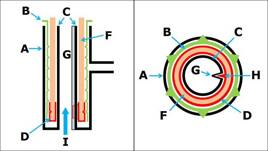
Diagrams illustrating the internal mechanism for wick movement
Left: The cross-section of the burner from the side
Right: The cross-section of the burner from above
Explanations to both pictures above:
| A | The outer shell of the burner; fixed component |
| B | The loosely inserted outer wick tube (rotatable); with the prong crown at the top |
| C | The inner wick tube, at the same time the tube for the central air draft from below; fixed, not rotatable; with guide notch G inside over the entire height |
| D | The small tube as wick carrier with the same worm thread as for the outer wick tube B; is inserted into B and is prevented from turning by bar H in the guide notch G |
| E | The 3 prongs of the gallery, which engage in the prong crown of B |
| F |
The tubular wick, fixed in the tube D |
| G |
The guide notch along the inner wick tube C |
| H |
The small bar inside the wick carrier tube D |
| I |
The inner air supply from below |
The Wick Knob with the Manufacturer's Logo
Almost all kerosene/paraffin burners have a wick knob, either to move the wick directly (wick drive with gears) or via a separate rack. Adjusting the height of the wick and thus precisely setting the flame brightness to a desired degree is almost always done by turning the wick knob manually. The wick knob became an integral part of almost all burners.
European burners almost always have a manufacturer's logo on their wick knob. This marking makes it possible in many cases to identify the manufacturer of the burner (but not of the whole lamp!). The logo is pressed into the wick knob. In some burners, you will find additional glass or ceramic inlays embedded in the brass wick knob and bearing the manufacturer's logo. There are even wick knob inlays made of a black synthetic resin (e.g. in the Gladiator burners by Societé Industrielle, Paris), which then swell up completely when treated with hot water for a longer period of time. The American lamps often do not bear a manufacturer's logo on the wick knobs, but on the flame discs of their burners.
Over time, burner manufacturers developed different logos for their burners in order to differentiate them well from burners of other types. There were manufacturers who used the once established logo as a trademark and hardly ever changed it (e.g. E&G with the two stylised dragons*, W&W with the wings swinging upwards, Hugo Schneider with the gear wheel in the middle of two wings extended downwards, etc.). Identifying the burners of these manufacturers is thus very easy.
*Note by Dirk Frieborg: Despite the striking resemblance to dragons, these are only seahorses, representing lucky signs of the Graetz family (confirmed by Max Graetz' granddaughter).
Identifying a burner manufacturer is problematic if there is only a very general designation on the wick knob, such as "Kosmos Brenner" or "Duplex", or if there is simply a star-like logo. These types of logo are often found on small to medium-sized Kosmos burners. It sometimes happens that the logo can be assigned to a well-known manufacturer, but the burner was produced by a completely different burner manufacturer (this is e.g. the case of Schuster & Baer, whose Reform Kosmos burner with the same logo on the wick knob was later produced and marketed by Brökelmann, Jaeger & Busse and Hugo Schneider - see photo with the back initials).
Another chapter in wick knob logos is the production of burners for other lamp producers, who did not make burners themselves, or even for renowned dealers who had lamps or lamp parts produced for themselves and then marketed them under their own name. Many of these burners then do not bear the logo of the actual manufacturer, but of the lamp producer or dealer. Famous examples for this are the high-quality burners by Wild & Wessel (Central Vulkan and Agni burners), which were supplied to the French company Robert & Vilette in Bordeaux and Paris. They bear the logo of this company (R.V. + anchor) instead of that of W&W.
A special feature are wick knobs of certain burner manufacturers that bear initials or any decorative patterns of their producers on their back, in addition to the logo that can be seen on the front. A famous example of this is the decorative cord of W&W, which appears on very many burners of this company (see photo in the subchapter The Kosmos Burner). Intertwined initials on the backs of the wick knobs are known to me from the following companies: SB for Schuster & Baer, SG for Schwintzer & Gräff, BJB by Brökelmann, Jaeger & Busse, HS for Hugo Schneider, LF for Lacroix & Ferrary. Flat burners by Young have a decorative pattern on the backs of their wick wheels. My Victoria burners by Stobwasser bear the letters F.S. My Columbus burner by C.F. Kindermann bears the letters C.F.K.&C.B. (the last two letters stand for Companie and Berlin).

Back side initials of some producers
(wick knob front and back respectively) The first three burners are identical.
From left: 16‘‘‘ Reform Kosmos burner, Schuster & Baer (initials SB)
16‘‘‘ Reform Kosmos burner, Brökelmann, Jaeger & Busse (initials BJB)
16‘‘‘ Reform Kosmos burner, Hugo Schneider (initials HS)
14‘‘‘ Kosmos burner, Schwintzer & Gräff (initials S & G)
10‘‘‘ Kosmos burner, Lacroix & Ferrary (intertwined initials LF)

Back side ornamentation or lettering by some producers
(wick knob front and back respectively)
From left: 14‘‘‘ Victoria burner, F. Stobwasser (letters F. S.)
20‘‘‘ Columbus burner, C.F. Kindermann (letters C. F. K. & C. B.)
11‘‘‘ Brilliant flat burner, Young (decorative pattern)
11‘‘‘ flat burner, R. Ditmar (inscription: Fabriqué en Autriche)
11‘‘‘ flat burner, R. Ditmar (inscription: Fabriqué en Allemagne)
In the catalogue section "Lamps of the Collection", each individual lamp is presented with its own profile. The photos next to the profiles show the logos of the respective burners.
A great help for me were the collected wick knob logos of collectors like Gerhard Bruder or Werner Pempel, who kindly published hundreds of logos on the internet. Unfortunately, Gerhard Bruder's website no longer exists. However, one can still access it in the form of a pdf file provided by Michael Pietschner in his website (see Literature and Sources ).