")
")
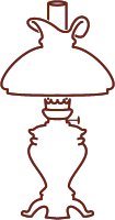
Kerosene/Paraffin Burners
The burner is without a doubt the most important part of a kerosene/paraffin lamp, because it burns the kerosene/paraffin and thereby generates the light, and this is the real purpose of a lamp, regardless of how big or small, imposing-decorative or simple it is. The economic constraints to achieve the maximum possible light output from as little kerosene/paraffin as possible have led to a stormy development and improvement of kerosene/paraffin burners.
The most common, most widespread burner shortly after the kerosene/paraffin lamp was launched was the simple flat burner. The name "flat burner" comes from the relatively narrow but flat wick that was used in such burners. The flat wick was invented in France towards the end of the 18th century (see chapter Argand's Oil Lamp) and was used for a long time in the oil lamps available at the time. After the advent of kerosene/paraffin as a fuel liquid, the burner with the flat wick had to be changed so that the air was thoroughly mixed with the volatile components of the kerosene/paraffin in a dome-like chamber (called "cap" or "sagger", see The Flat Burner). This gave birth to the “flat burner” that is found today in many older kerosene/paraffin lamps. This type of burner was for a certain time the "sole ruler" in the still young history of the kerosene/paraffin lamps until the round wick burners came onto the market. They could shape wider flat wicks into a hollow wick that, thanks to the internal airflow that was now possible, burnt with a better, i.e. brighter flame. The round wick burner (referred to as “round burner” throughout the whole following text) then conquered the market in the following decades until they were in turn displaced from the market by mantle burners, as these burners produced a light whose brightness could not be achieved by any conventional burner. An even more innovative, technically fully developed improvement of the light brightness was finally achieved with lamps that gasify the fuel under pressure and thus make several incandescent mantles in one lamp glow.
The era of the kerosene/paraffin lamp ended when the electric light came on. The electric light bulbs did not need a burner or fuel to generate light. A glowing metal wire and electric current had replaced the burners of the kerosene/paraffin era. Since then, mankind has enjoyed electric light. It's so easy to turn on a light bright enough with a simple switch on the wall. The times were forgotten with the whole circumstance of filling the lamp, cleaning the chimney, lighting the burner, etc. A single lightbulb could replace several conventional kerosene/paraffin lamps. One can hardly imagine how faint the light from a burning flame from a kerosene/paraffin lamp is compared to that of an even small light bulb. When the Swiss Ami Argand succeeded in introducing his revolutionary burner, his contemporaries were delighted how bright this flame was compared to the simple oil lamp flame. Some even complained that the brightness was too high, which would damage the eyes! How would these people feel if they could look into our light-flooded world for a few moments today?
And these electric light bulbs, as we have long called them, are currently being replaced by a completely different type of light generation, namely by LED lamps, which combine the usual convenience with enormous economy, because they only consume a fraction of the electricity to produce an equivalent brightness.
After this short excursus on the lighting history of the last 250 years, let's go back to our old kerosene/paraffin burners: It is remarkable that initially two geometric terms, "flat" and "round", characterize the whole world of burners in conventional kerosene/paraffin lamps. As a result, experts agree that there are two main types of burners that have been used in these lamps:
a) Flat burners
b) Round burners
I expand this division in two groups as follows to allow a more meaningful distinction:
a) Flat burners
b) Duplex burners
c) Kosmos burners
d) Burners with flame discs
e) Other burners
Each of these burner types is presented in a separate chapter.
The Three Most Common Burners with Their Parts
Here I would like to show the general structure of the kerosene/paraffin burners schematically at the three most important representatives - somewhat anticipating the individual chapters of the burners.

Schematic structure and parts of the most important kerosene/paraffin burners
Left: The flat burner
Center: The Kosmos burner
Right: Burner with a flame disc (wick drive here with gears)
1. Burner thread: Almost all burners have a thread at the bottom with which they can be screwed into the collar of the font. Exceptions are duplex burners with a bayonet fitting and smaller clip-on burners.
2. Wick knob ring: The wick knob ring is firmly attached directly above the burner thread. The wick knob ring (my own designation; not a common nomenclature) is so named because it usually carries the wick knob of the burner. The gears with which the wick can be moved up or down are located in a chamber within this ring (wick drive).
3. Wick knob: The wick knob is the outer wheel with which you can turn the inner gears to move the wick. Another term for wick knob is wick wheel.
4. Basket thread (see the next photo)
5. Basket: The burner basket is screwed to the basket thread, through whose air openings (holes and slots of different patterns) the air flows in and improves visibly the combustion of the kerosene/paraffin on the wick as an external and internal air supply. This basket can be concave (as with many flat burners), convex (as with many round burners with and without a flame disc) or even cylindrical (as with white-light burners).
6. Gallery: The burner basket is usually firmly connected to the burner gallery. The gallery contains bendable prongs (or teeth) that hold the inserted glass chimney in place. The Viennese flat burners do not have any prongs, but rather rectangular lamellas, which in turn are somewhat movable. The shade holders (e.g. globe holders) are also attached to this gallery. For all burners with a lifting platform (see subsection Raiser and Extinguisher) the basket and gallery must be separable from each other. In the case of the burners without a lifting platform, they are usually firmly joined together. There are exceptions, however, where the basket is firmly attached to the wick tube and the gallery is then screwed to the basket or attached with a bayonet connection.
7. Wick tube: Inside the basket and firmly connected to the basket thread is the wick tube, which contains the wick that burns at the upper end. With flat burners, the wick tube is a flattened rectangular pipe, the dimensions of which correspond in width and thickness to the flat wick used. On the other hand, the wick tube with the round burners consists of two round, concentric tubes (the inner and the outer wick tube) in which the flat wick is formed into a round wick. The wick tube in the so-called center-draft burners is constructed differently (see below).
8. Side air inlet: The diameter of the wick tube is larger at the bottom than at the top to make room for a side opening. This side opening ensures the internal air supply to the flame and is the most important difference to the burners with central air flow. The opening for the side air inlet can be triangular as with Kosmos burners or rectangular as with the larger flame disc burners.
9. Cap: An essential part of the flat burner is the dome-shaped cap, which is usually detachably placed in the basket and has an elongated slit at the top, from which the flame comes out. The cap serves to improve the mixing of the air flowing in through the basket slots with the gaseous components of kerosene/paraffin. Only flat burners and duplex burners have a cap.
10. Deflector: The deflector is a round pipe that is placed inside the burner gallery around the wick tube. It is an integral part of the burner gallery for all round burners, with or without a flame disc. The task of the deflector is to direct the external air supply even closer to the outer flanks of the flame and thus to intensify the contact of the flame with air.
The deflector is one of the main distinguishing features between Kosmos and flame disc burners. In all burners without a flame disc, the deflector is so short that its upper edge does not protrude beyond the gallery teeth; so it is not visible if you look at a Kosmos burner from the side. In the case of the flame disc burners, the deflector is extended upwards so that it is visible when looking at the burner from the side. In the case of 15-line burners, the deflector sometimes protrudes clearly, but sometimes barely visible, beyond the jagged edges of the gallery. In the case of larger burners with 20 lines and above, it is even a dominant part of the burner and covers the wick tube in such a way that only the upper edge of it can barely be seen. Sometimes the deflector is even longer than the wick tube. The advantageous reasons for this are explained in the chapter Distinction between Kosmos and Flame Disc Burners.
11. Flame disc: With the flame disc burners, the wick tube at the top carries the now obligatory flame disc (also referred to “flame spreader” or “flame diffusor”). Flame discs can have very different shapes and sizes (see also the section Flame Disc Burners). The main task of the flame disc is to direct the internal air supply more intensively to the inner flanks of the flame.

Wick tube design at round burners
Left: The wick tube of a Kosmos burner (tapering conically upwards)
Center: The wick tube of a flame disc burner (cylindrical in the lower part; wick drive here with a gear rack)
Right: The inner wick tube of a center-draft burner (the central air tube of the font; see below)
4. Basket thread (not visible in the schematic pictures above): Above the wick knob ring there is again a firmly joined thread (not with flat burners, but with round burners) on which the burner basket is screwed. Therefore I call this thread “basket thread” to distinguish it from the burner thread. The basket thread has the same size as the burner thread on many burners. There are exceptions, however.
12. Wick drive with gear rack: The vast majority of small to medium-sized burners have 2-4 gears (toothed wheels) inside the wick knob ring, which move the wick when one turns the wick knob. In the case of large, high-quality flame disc burners, on the other hand, a cylindrical tube with a rack attached to it has been introduced to facilitate the movement of the wick in the wick tube. I explain the different types of wick drive in detail in the subchapter Wick and Wick Drive.
Burners with Central Air-Draft
The burners in the lamps with the central air flow differ significantly from the burners with the side air supply. While the wick tube with a side air inlet consists of two firmly connected, concentric tubes (see above), the central draft burners consist of two completely separate tubes. The outer wick tube is still fixed to the burner itself, exactly as described above for the wick tube. The inner wick tube, on the other hand, is not connected to the burner at all, but is an integral part of the font. It is a long, cylindrical tube that extends through the font to the bottom and is open at the bottom. The air flows up through this lower opening and acts as the inner air supply. This type of burner can be seen as the continuation of Argand’s oil burner in a modified form. The tubular wick is located between the inner (attached to the font, not removable) and the outer (attached to the burner basket, removable together with this) wick tube. These burners are commonly called center-draft burners.

Schematic comparison between side-draft and center-draft burners
Scheme A: Side-draft burner on a classic font that is closed at the bottom
Scheme B: Center-draft burner on its specific metal font with the central air tube
Explanations to the schemes in the picture above:
Scheme A:
1 = Classic kerosene/paraffin font, closed at the bottom
2 = Side-draft burner with a side opening on the wick tube
3 = The inner wick tube of the burner, firmly soldered to the burner
4 = The outer wick tube of the burner, also firmly soldered to the burner
5 = Flat wick between the two concentric wick tubes (folded into a round shape in the burner)
6 = Glass chimney
7 = Inner air supply through the side opening of the wick tube
8 = Outer air supply through the openings of the burner basket
Scheme B:
9 = Metal font of the center-draft burner with the central air tube, open at the bottom
10 = Center-draft burner (can only be used on this font)
11 = Central air tube, soldered to the font (works as the inner wick tube)
12 = Outer wick tube of the burner, soldered to the burner
13 = Tubular wick between the outer wick tube and the inner, central air tube
14 = Inner air supply from below through the central air tube
Further Information
Before we close this chapter, I would like to mention a few important aspects.
A) The burner with all its components is almost always made of sheet brass, as brass can be easily processed into sheet metal of any thickness, punched very easily and shaped into all kinds of shapes. Also, it doesn't rust like iron. The only disadvantage of brass is that if you don't clean it from time to time it will tarnish and turn brown to dark brown over time. In the early years of the kerosene/paraffin lamps there were also flat burners that were made entirely or partially of iron. These burners were probably intended to be used with the cheaper lamps. There were also burners made of the usual brass sheet that was nickel-plated, chrome-plated or even silver-plated, depending on which colour combination the manufacturer was aiming for with his lamps. Very high quality British lamps often had silver-plated burners, which were then protected against tarnishing with a transparent protective lacquer.
B) The burner parts are almost always diligently soldered together by hand during manufacture. That was a tricky job because the parts had to be soldered in their exact positions without deviations. A few parts could also be mechanically pressed together to form a unit. Soldering was almost always done with soft solder (lead solder). Hard solder was only used for the burners for oven lighting. Therefore, be careful when cleaning and repairing burners. They should not be heated above 160-180 ° C for a long time.
C) In the next few chapters you will repeatedly discover abbreviations for company names. Experienced collectors know immediately which company is meant when they see such an abbreviation. A number of abbreviations are listed alphabetically here:
| B&H | Bradley & Hubbard, USA |
| B&L | Brendel & Loewig, Berlin |
| B&R | Bünte & Remmler, Frankfurt |
| BJB | Brökelmann, Jaeger & Busse, Neheim |
| C.H. | Carl Holy, Berlin |
| E&G | Ehrich & Graetz, Berlin |
| H.S. | Hugo Schneider, Leipzig |
| K&G | Kaiser & Gundlach, Berlin |
| K&T | Kästner & Töbelmann, Erfurt |
| L&B | Lempereur & Bernard, Liège and Lépine & Bourdon, Paris |
| L&F | Lacroix & Ferrary, Caen |
| M&B | Maris & Besnard, Paris |
| M&W | Matthews & Willard, USA |
| O.M. | Otto Müller, Berlin |
| P&A | Plume & Atwood, USA |
| Q&H | Quaadt & Hirschson, Berlin |
| S&B | Schuster & Baer, Berlin |
| S&G | Schwintzer & Gräff, Berlin |
| S&S | Schubert & Sorge, Leipzig |
| S.I. | Societé industrielle d’articles d’éclairage, Paris |
| T&B | Thiel & Bardenheuer, Ruhla |
| W&B | Wright & Butler, Birmingham |
| W&W | Wild & Wessel, Berlin |
D) Some important notes for non-Germans people:
I have always left all German trademarks for lamps and burners unchanged in their German spelling without ever translating them into English. Examples: The German Concurrenz-Brenner is "Concurrenz burner" in the English text and not "Concurrence burner". The Austrian Favorit-Lampe is "Favorit lamp" and not "Favourite lamp" in the English text.
All German company names and burner names that contain the German letters ä, ö and ü are also spelled with these letters unchanged in the English text. Examples: “Kästner & Töbelmann” as a company or “Bürger burner” as a burner name. Sometimes these German letters are also written as ae, oe and ue to facilitate spelling in other languages that do not have these letters. For example, Kästner & Töbelmann is often written as "Kaestner & Toebelmann" (especially on the wick knobs of this company).
I have left the German burners that were marketed in the UK under a different name with their German name. For example: I have not written “Central Vulkan” burners by Wild & Wessel with their British brand name "Globe Vulcan", but left them with their German name. The same applies to Volksbrenner by Carl Holy, which are called "Wizard" in the UK.
I have left R. Ditmar's "Sonnenbrenner" as it is, since this brand name consists of one word. For all other brand names consisting of two words, I have written "burner" instead of Brenner in the English text. For example, Titus-Brenner in German became Titus burner in English.
I have included the following company names unchanged in their original spelling in the English text: Gebr. Brünner; Gebr. Wolff; Moreau Frères. Gebr. is the abbreviation of Gebrüder, which means “brothers” in English. The same applies to the French word Frères.
And finally, a correction: The company name Ehrich & Graetz has nothing to do with the first name Erich or Eric. "Ehrich" is a family name and must be written with the letter h. This is usually misspelled in the USA. Also, the German surname Kleemann (the famous manufacturer of student lamps) is usually americanised as "Kleeman", which is not permissible.